UPDATES FROM THE JS-25 PLATFORM

New features & software for the next generation of sawmill scanning
In order to make the world’s best sawmill scanner better with the JS-50, we’ve had to make some changes that break compatibility with our previous JS-25 series.
Since releasing the first JS-20 scan heads back in 2002, we’ve learned a lot about how to make a scanner that is simple and reliable even in the rough & tumble world of sawmill automation. Much of what we’ve learned has been incorporated incrementally into firmware updates, and compatible platform updates, like the JS-20 to JS-25 update. But some of our latest improvements were simply not possible without breaking backwards compatibility. So while there will be some additional effort for integrators transitioning from the JS-25 to the JS-50, there are many more benefits to the new architecture.
benefits of the changes will be called out with the thumbs up icon
features enabled by the changes will be called out with the handshake icon
Integrator Changes for JS-50
JS-50 and future model JoeScans will now use our new Pinchot API. JCam will still be the API for JS-25 and JS-20 model scanners.
For your reference, the latest JS-50 Pinchot API, tools, and documentation can always be found at api.joescan.com
Orientation
Orientation, what was called calibration in JS-25, is not persisted in JS-50.
For JS-50, this property is stored in the optimizer computer and sent to the scan head upon connection. You can think of this as the transform so that instead of returning profile points relative to each individual sensor, the points live in a common mill coordinate system.
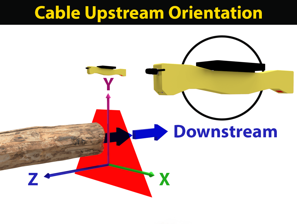
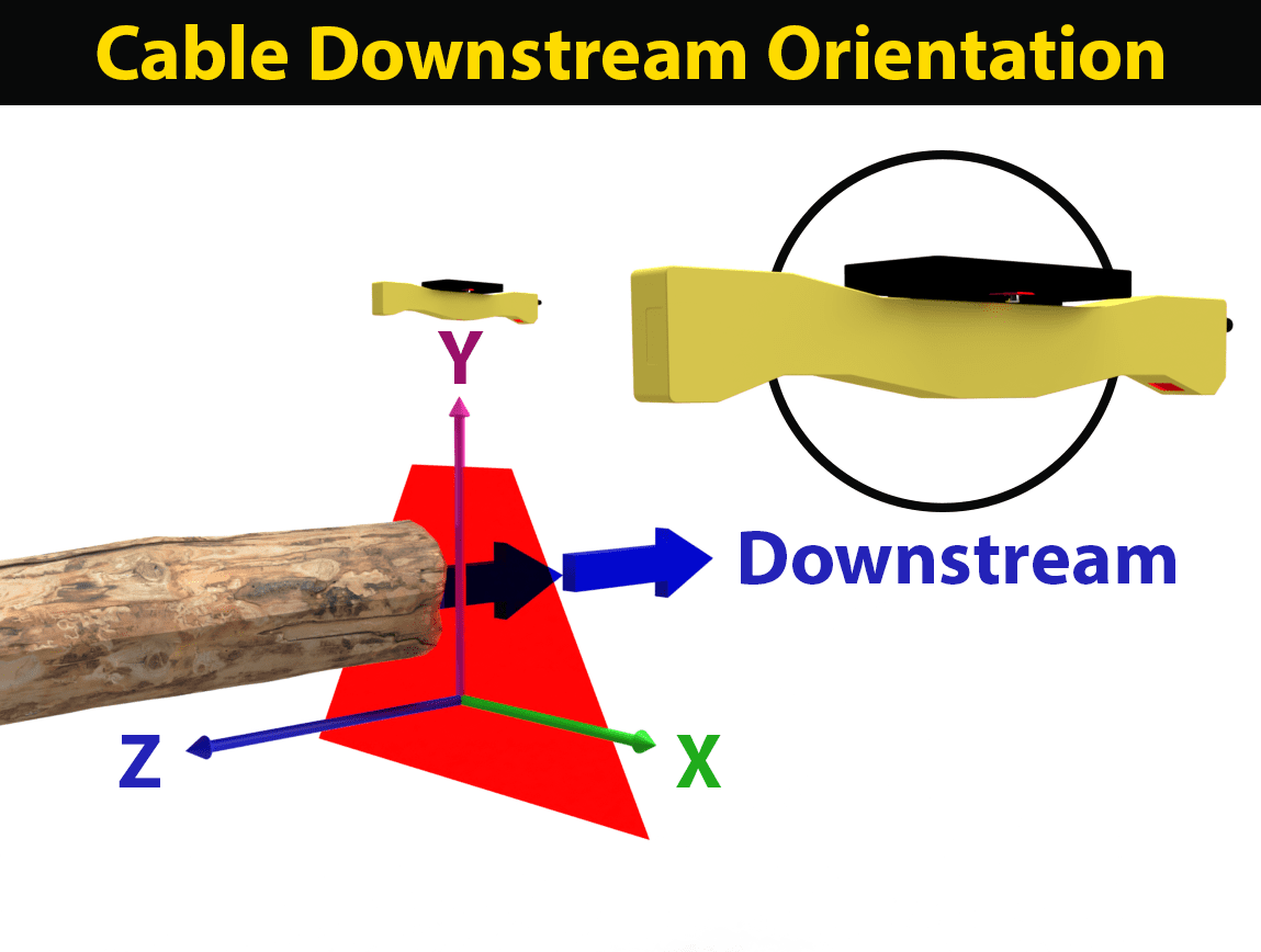
The orientation consists of 4 components:
- a flip of the coordinate system depending on if the cable is up or downstream
- a rotation in the laser plane
- an X offset
- a Y offset
The cable upstream or downstream is just a description of how the scan heads are mounted in the system. The other three parameters can be given a default value based upon the scan frame layout. However to achieve accurate results, newly installed scan heads will need to be calibrated by scanning a known-shaped target at a specified location in the mill coordinate system. The optimizer can do this with their own routines, or we provide calibration routine the optimizer can use to assist in calibrating the orientation parameters.


Cable Upstream/Downstream setting ensures coordinates stay the same.
A single, integrated orientation schema was driven by the repeatability of the QuikLock mount system introduced with JS-50. Essentially, it’s easier and quicker for the orientation to be passed to the individual scan heads without having to manually re-configure new heads.
single integrated configuration, simplifies hot swaps & reduces downtime
Configuration
Likewise for scan head configuration, which was previously contained in the param.dat on the JS-25, as this method will not persist on the the JS-50 platform. In fact the param.dat file will not exist for JS-50 scanners.
Instead all scan head configuration settings are passed in via software through the Pinchot API. Configuration can either be hard-coded, made part of the optimizer’s configuration data, or automatically generated based upon higher level configuration settings. Configuration settings will not persist on the scan head after it is rebooted, but will be passed through the Pinchot API from the optimizer’s computer when it connects.
The biggest difference for integrators will be setting the scanner phasing. With JS-25 param.dat the scanners were assigned a scan phase. All the scanners in a given phase would scan simultaneously. For JS-25 the software would automatically determine when to fire each phase, based on the phase table and the MaxLaserOn times. With the JS-50 the optimizer only provides a time offset. The optimizer software is responsible for determining the proper phase timing and generating the offset for each scanner. We provide documentation describing how to calculate phasing offsets for various systems types.
improves system design flexibility, simplifies hot swaps & reduces downtime
IP Addresses
The JS-50 also takes a different approach to assigning IP addresses to the scan heads.
In the JS-25 these were set using a proprietary JSConfig software tool. With the JS-50 IP Addresses are either assigned via a collaborative standard technology called ZeroConf, or using DHCP. But in practice the optimizer no longer needs to be concerned with IP addresses.
In the Pinchot API, the connections are made based upon the scan head’s serial number. We recommend having the scan heads on an isolated network that is only accessible from the optimizer PC.
reduces configuration time, simplifies troubleshooting, reduces downtime
Cables
On the JS-25 the power, encoder and synchronization signals were provided over a separate 8 conductor cable. This cable was then wired into terminal strips at the junction box.
There were two main downsides to this approach. First, putting together and wiring up the junction box was time consuming with much of that working having to be done onsite and slowing down the startup. Second, cables are the largest source of failure. On the JS-25 if either cable was faulty, the scanner would fail to function. Additionally, when a scanner is not functioning correctly you have two cables to check.
The JS-50 improves on this by going to a single cable that terminates into an industry standard gigabit Power over Ethernet (PoE) switch. This change makes startups faster and simpler, improves system reliability, and simplifies problem diagnosis.
improves system reliability, speeds up start-ups, simplifies troubleshooting
PoE Network Switch
The JS-50 PoE cables mentioned above must be connected to a PoE Network Switch in order to power the scan heads and transmit data. We built our scanners to comply with the IEEE 802.3 af Power over Ethernet industry standard. This standard ensures compatibility with a large number of commercially available network switches that you can order from any number of online retailers.
You will want to make sure the total power output of your switch can supply each scan head with the full 12.95 watts designated in the standard. Many switches will advertise the 802.3af standard, but will not be able to provide this power level to all of their ports at the same time. Practically, this means you may need to use a switch that has more ports than you have scanners and ScanSyncs in your system.
Keep this formula in mind when shopping for PoE switches for a specific application:
Total switch power rating ÷ number of JS-50 heads in your system > 13 watts
standardizes components, enables single cable simplicity
Encoder Input
With a JS-25 system, encoder inputs were distributed directly to all the scan heads in the system via the power cable.
With the JS-50 the encoder is connected only to a ScanSync module which then distributes the encoder location along with timing synchronization over Ethernet. To ensure that the encoder and time synchronization are accurate, the ScanSync and all the JS-50 scan heads in the system must all be connected to a single Ethernet switch.
The ScanSync device features error code LEDs on the housing. These lights can help diagnose set up and connection problems with the encoder during start ups, or while troubleshooting.
Currently, we only support one ScanSync, and therefore one encoder per system. Future updates will add support for stamping each profile with multiple encoders. For a headrig carriage this will allow having location stamps for the knee positions, and the carriage. If you are interested in using multiple encoders please contact us.
speeds up start-ups, improves system reliability, simplifies troubleshooting
Synchronized Scan Modes
The JS-25 supported a number of synchronized scanning modes, based on the encoder motion, time, or synchronization pulses.
The JS-50 only supports a time-synchronized scanning mode. After the scan heads have been added to the system, and configured with phase offsets, a call is made to start the system scanning at a given rate.
necessary for ScanSync device schema
TCP / UDP Communications
In the JS-25 the communications with the scanners was done over TCP. With the JS-50 communications are over UDP.
The big reason for this change is that with TCP when a packet is dropped, the retransmission can delay data for 250ms or more. On a high speed trimmer this is an intolerable delay and almost impossible for the optimizer to handle gracefully.
With the JS-50’s UDP implementation, a single dropped packet will at most drop the single profile. In practice it will produce a profile with some of the profile points missing. For many optimization systems this will require no special logic to handle. We do provide fields in the profile reporting if there are missing profile, and do recommend that the optimizer report if there are an abnormally high portion of dropped packets. It should be rare to have more than one in a million packets dropped.
improves network speed & reliability
CPU Usage
Because the JS-50 uses UDP, and profiles are sent immediately upon being taken, the optimizer PC must be continuously listening and processing the UDP packets as they arrive. The new API does this in the background on a set of worker threads, and queues the profiles locally for the optimizer.
On a large system with a high scan rate this can consume a non-trivial amount of CPU. However the new Pinchot API is designed to be efficiently multi-threaded. For large systems with high scan rates, such as trimmers, we recommend using larger workstation or server-class machines with 8 or more cores.
required for faster scan rates with increased data resolution
Data Transfer Rates
With the higher data rates and scan resolutions of the JS-50, the 100Mbit Ethernet used by the JS-25 is no longer sufficient.
The JS-50 now uses gigabit Ethernet. Therefore a gigabit switch is required. For any high performance systems we also recommend the switch have a 10Gbit up-link port that is connected to a 10Gbit NIC in the optimizer PC.
required for faster scan rates with increased data resolution
Versioning Compatibility
Versioning is also handled differently with the JS-50 compared to the JS-25.
With JS-25 we attempted to make any version of API compatible with any firmware revision. This made improving and maintaining the firmware and API difficult, and it locked us into design choices.
With the JS-50 we require that the Pinchot API version and the scanner firmware version be the same. This will give the optimizer the certainty that they are using a tested known good API/Firmware combination, and give JoeScan more flexibility to improve the product.
improves system reliability & simplifies troubleshooting
In Summary
So what does this mean for integrators already familiar with our JS-25 platform? Unfortunately, it means that you’ll have to write new code to interface with the JS-50’s Pinchot API.
However, we are confident that these changes will deliver fantastic results for you and your sawmill clients. We’ve worked hard to make JS-50 and Pinchot a robust platform that we will be able to support and build upon for years and years to come.
Have additional questions? Want to request specific features? Reach out. We’d love to hear from you.
Our goal is to create a platform that is reliable, easy to work with, and gets the job done for sawmills all over the world. Partners like you play a big role in helping us do just that.


Leave A Comment
You must be logged in to post a comment.