A LOOK AT THE FUTURE OF TRANSVERSE SCANNING
Adapted from a presentation Joey gave at the 2019 AHMI annual conference in White Springs, West Virginia.

In this post we will explore the trade-offs of two different types of lasers used for transverse 3D laser scanning in sawmills: multi-dot lasers and line lasers.
The JoeScan engineering team undertook this examination as we built a technology roadmap for developing the next generation of sawmill scanners. We wanted to know which type of laser would best deliver the specifications and results that sawmills need.
We’ll gloss over the introductory “3D scanning 101” portion of the presentation and get straight to the meat and potatoes of the topic.
You can find more on the basics of 3D scanning for sawmills by clicking here.
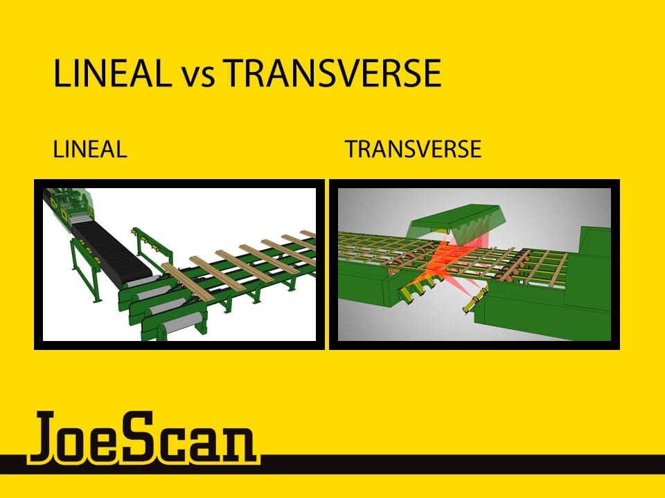
Transverse scanning itself offers some unique trade-offs versus lineal scanning.
It allows you to scan large amounts of fiber very quickly, but it can be difficult to gather enough high quality data because of this fast pace.
Also, steep wane can be difficult to distinguish from square boards by many traditional scanning methods.
The most important parts of the board for transverse 3D scanning are the leading and trailing faces. This is where you will find wane that needs to be trimmed off.
These faces are difficult to scan because of their location and size. Scanners are placed above and below the boards being scanned, so they often have a better view of the top and bottom faces of a board. The leading and trailing faces also represent a smaller percentage of the surface area than the top and bottom of the board.
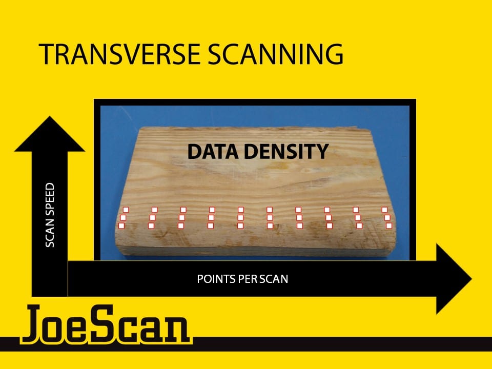
Data density can be defined as the number of 3D points your scanner collects over a given area. It is important for this number to be high so that your optimizer has enough data to make decisions on. Low data density can lead to missed defects and poor decision making.
For transverse scanning, across the board data density is a function of your scan speed. Each scan will add a new row of data along the board to your 3D profile. Thus, the faster you scan, the more rows of data you will have for a given board width, and the closer these rows will be to each other.
Along the board data density is a function of your scanner’s camera resolution and the number of laser points this camera has to look at.
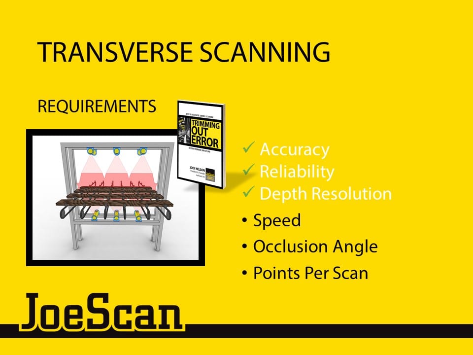
These are the metrics that are most important for transverse scanning in sawmills. We will be using them to compare the two types of lasers available.
For many years now, accuracy, reliability, and depth resolution have been achievable with both multi-dot and line lasers. The laser types begin to separate when we look at speed, occlusion angle, and points per scan.
Speed refers to the scan speed of the laser scanner: how many scans are captured per second or how close the rows of data are to each other.
Occlusion angle is a measurement of the separation between the laser and the camera. A high occlusion angle can create instances where board features can block (or occlude) the cameras ability to see other areas of the board.
And finally, points per scan means the number of 3D points we can gather along the board with a single scan: how close the columns of data are to each other.
We’ll now begin to look in-depth at both types of lasers.
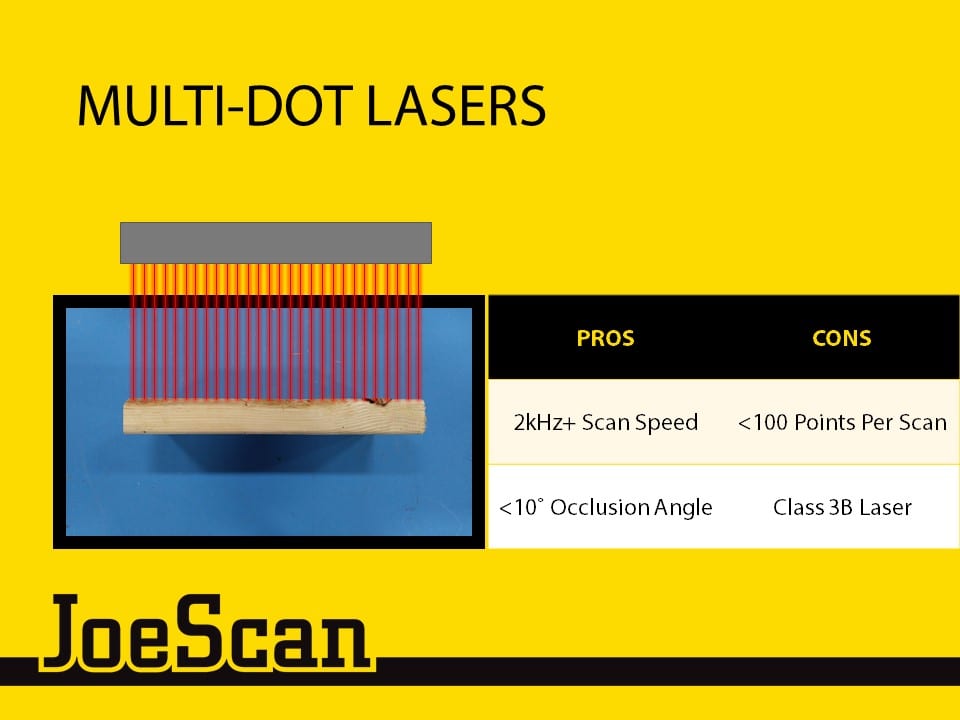
Multi-dot lasers project a series of single laser points, spaced evenly along the board.
They have historically been utilized for transverse scanning because of their high scan speeds.
However, the trade-off is that they do not collect a large number of along-the-board points per scan. As you can see, they have a fixed number of points, with gaps between them. Because of this, they cannot provide an accurate length measurement.
Another downside is that they feature class 3B lasers, which require emergency shutouts and other safety hassles.
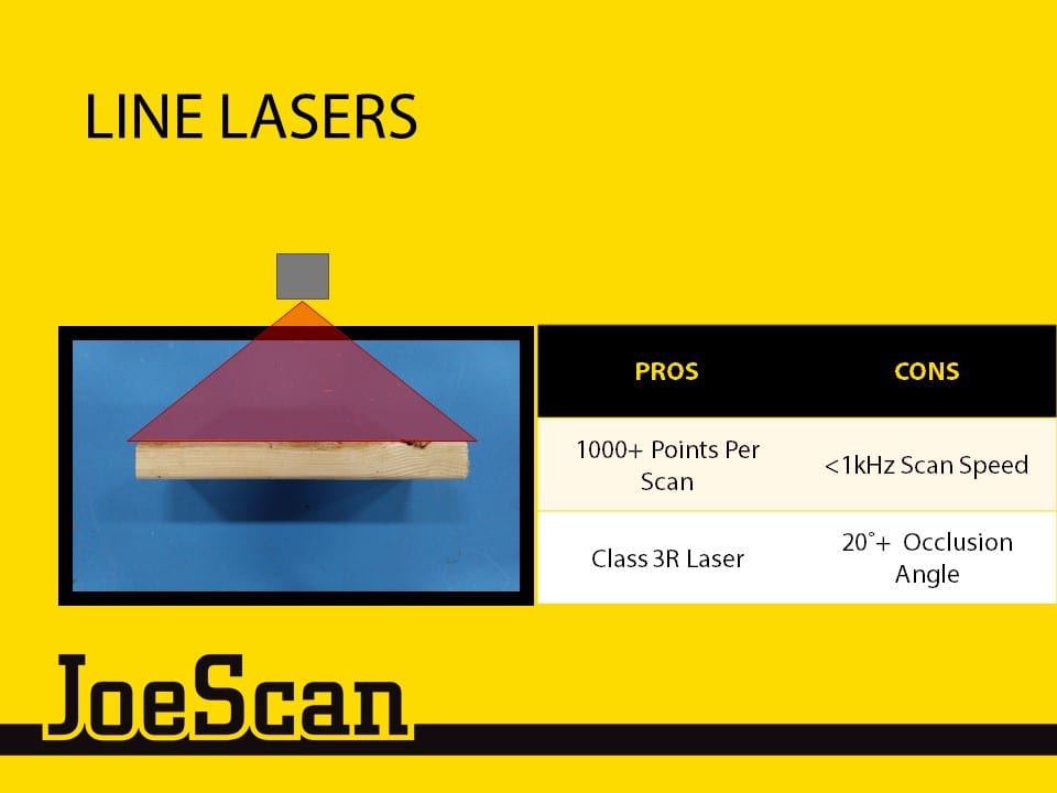
Line lasers project a single sheet of light along the board.
They have historically been prized for the data density they can achieve. The line laser is a continuous set of points that is only limited by the resolution of the sensor looking at it. This makes them ideal for many lineal scanning applications.
The trade-off here is that it takes time to process all of that data, and they have typically been slower than multi-dot laser scanners.
Line laser scanners also have traditionally featured a higher occlusion angle than multi-dot lasers, which means some sections of the board may be blocked by steep wane.
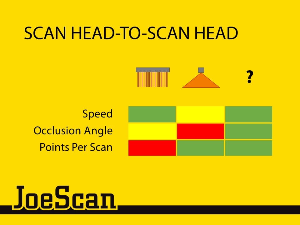
Here is the matrix of the strengths and weaknesses of both types of lasers.
As we looked at developing the next generation of transverse sawmill scanners, we wanted a solution that performed well across all of these metrics. But how could we get there?
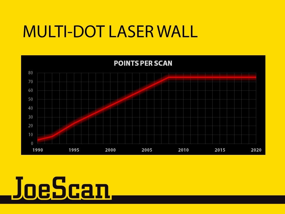
One potential solution would be to improve the along the board data density of multi-dot laser scanners.
By 1995 the industry was seeing 1 inch spacing between lasers with multi-dots (meaning the scanner was gathering 1 data point per inch of board length). Over the next 15 years, this spacing was reduced to about 0.3 inches.
In the last 10 years though, we’ve seen no real improvements in multi-dot point density.
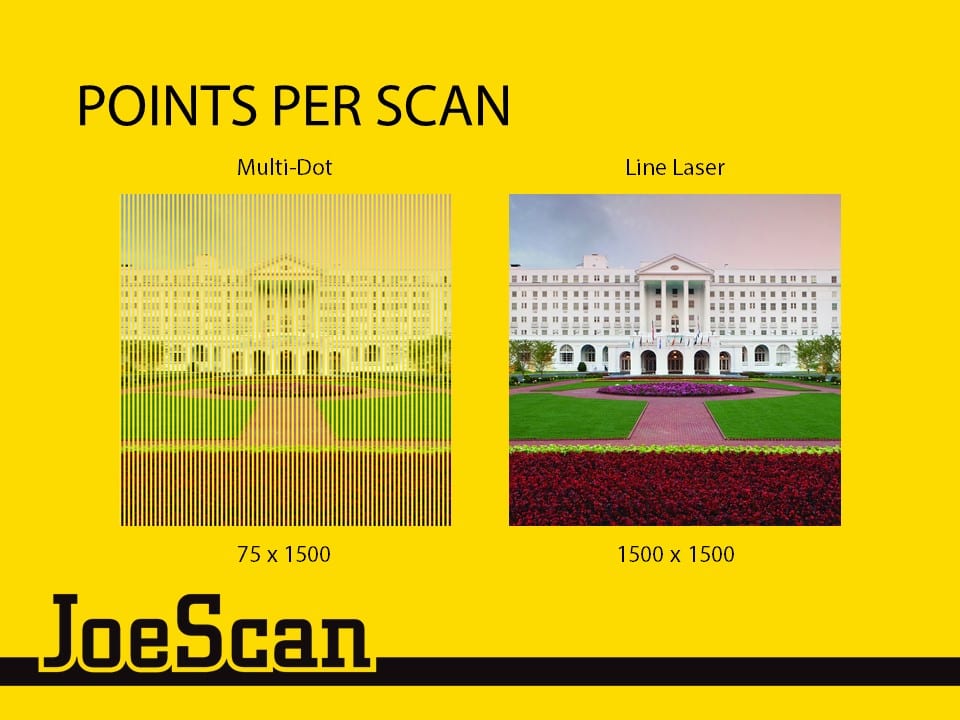
Here we see a visual representation of what this difference in along the board data density looks like.
Because the multi-dot laser points are physically separated from one another, we cannot get a better resolution image than this. There is a physical limit to how many individual lasers can fit in a given package size. We’ve hit a wall with multi-dot lasers.
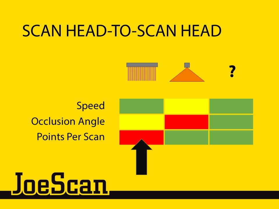
If points per scan are a limiting factor for multi-dot lasers, they don’t make a good platform for our next generation sawmill scanners.
We then turned to line lasers. How can we improve the speed and occlusion angle of line laser scanning?
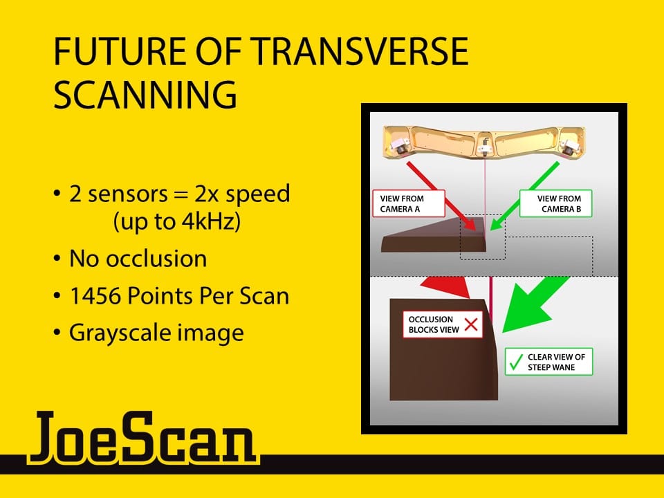
We were able to solve both the scan speed and occlusion angle limitations of line lasers with a single design solution: dual cameras.
Two sensors are able to provide twice the across the board scan data of single camera systems.
By placing the cameras on opposite sides of the scanner body, there is built-in coverage for occlusion. Essentially, each camera can cover the other’s blind spot. If the laser is touching the board, one of the cameras will see it, no matter how steep the wane is
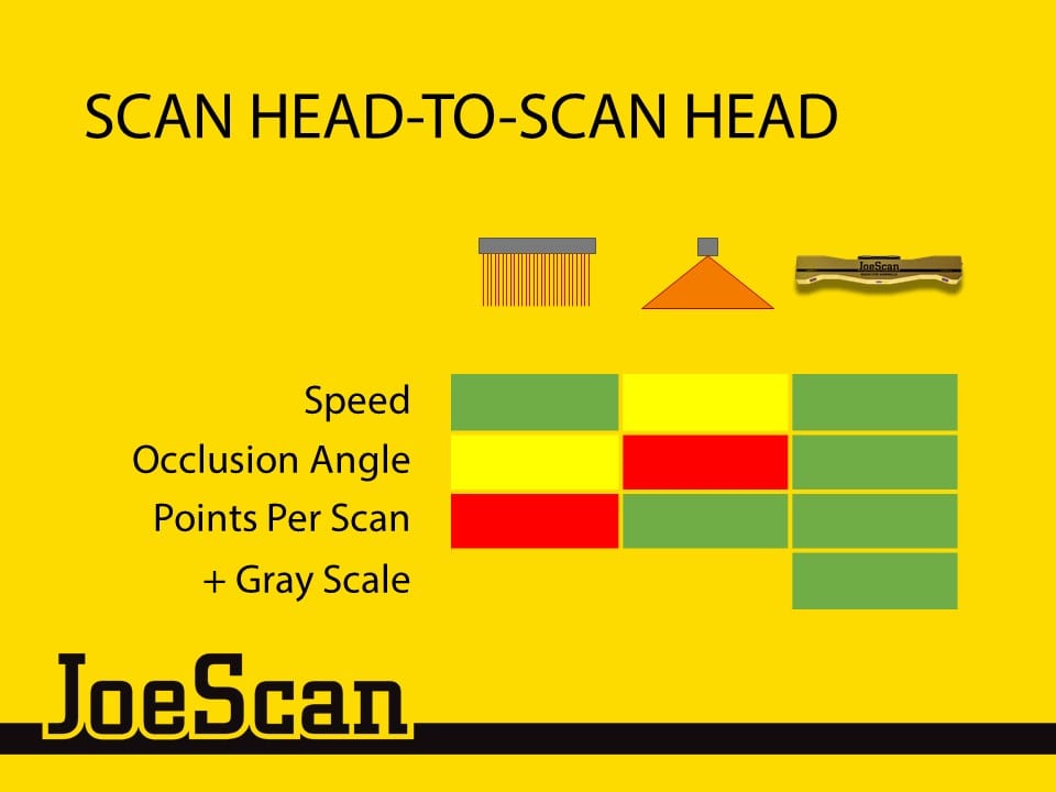
Our engineering team captured these lessons in the design for our latest JS-50 WX scan head.
We also included the latest in high definition sensors in our cameras. This gives us tremendous along the board data density. It also allows our scanner to generate grayscale images that can be used for detecting knots and other non-geometry defects, without the need for a separate vision module.
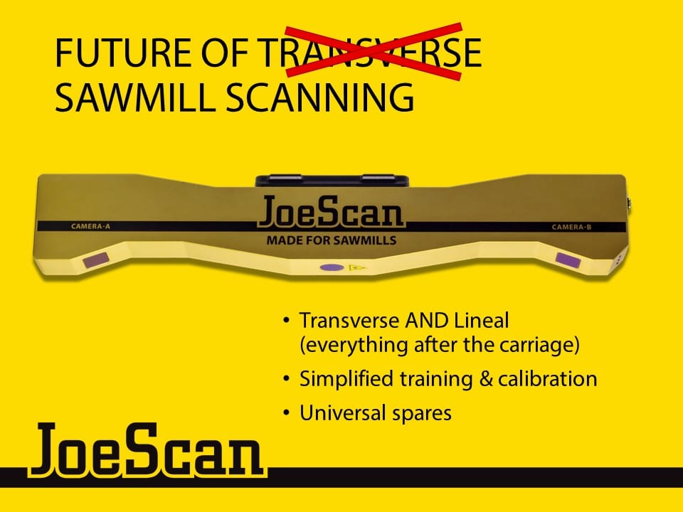
These improvements to line laser scanning make the JS-50 WX a very versatile scanner.
It is fast enough for transverse scanning, but also provides enough data for very precise lineal scanning.
In fact, we envision a sawmill that uses just this one model of scanner for every machine center (excluding the carriage). This single-scanner mill could simplify their training and calibration procedures, and keep just a few spare scanners on hand that could be used anywhere on their line.
Do you have questions about the different kinds of lasers used in 3D scanning? Feel free to contact us via email, or leave a comment below.



Leave A Comment
You must be logged in to post a comment.